
IIoT : Designing Industrial Embedded Electronics for Reliability
Written by
in
IIoT : Designing Industrial Embedded Electronics for Reliability
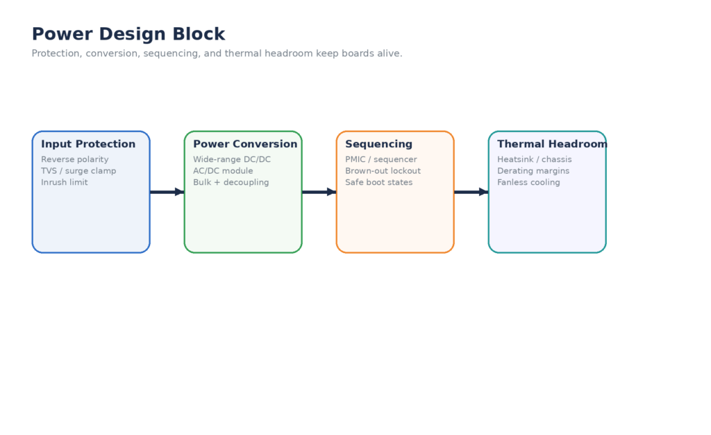
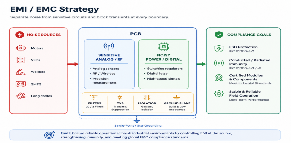
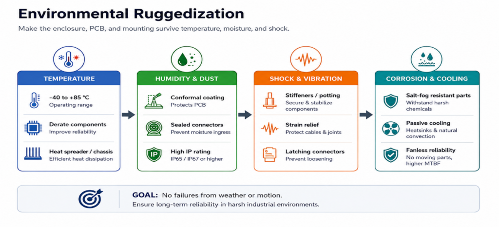
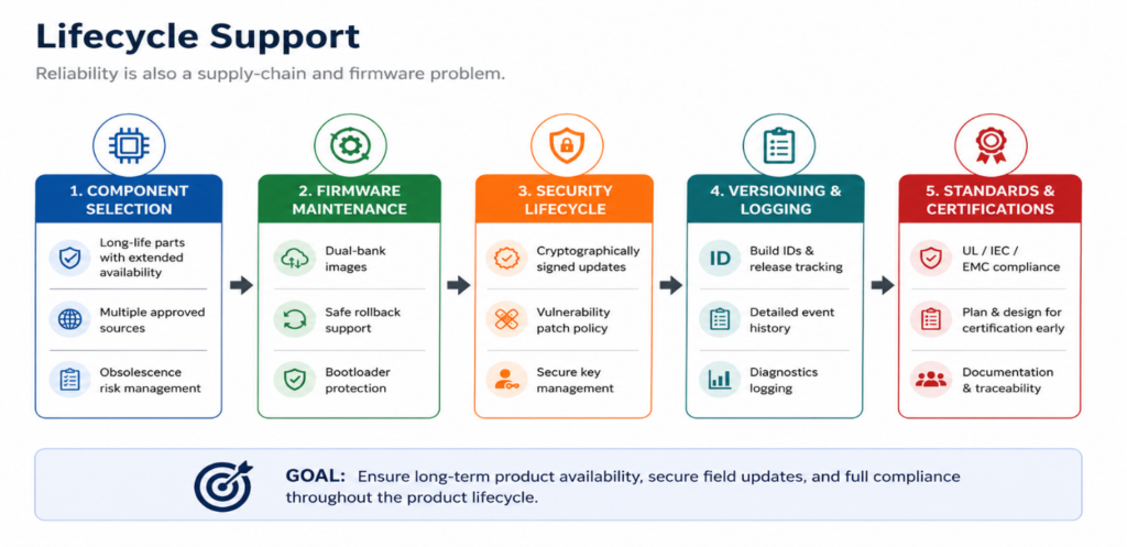
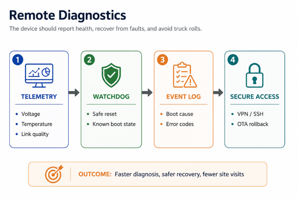
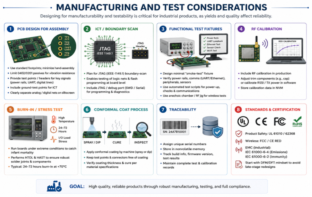
Industrial IoT (IIoT) embeds sensors, controllers, and communication modules into factory, utility, and field equipment. Unlike consumer IoT devices (smart home gadgets, wearables, etc.), IIoT devices run in demanding settings (factories, power plants, oil fields, transportation) with long lifetimes and high reliability requirements. Failure of an IIoT device can have catastrophic consequences (safety incidents, costly downtime), whereas a consumer device failure is usually only an inconvenience. This shifts design priorities: industrial devices must survive extreme environments, electromagnetic noise, power disturbances, and remain serviceable remotely. Figure 1. Consumer IoT vs IIoT design priorities. The comparison above underscores that every subsystem must be ruggedized and engineered for longevity in industrial designs, not just the sensing or compute functions. Power Design for Industrial Embedded Systems Wide Input Ranges & Robust Sources: Industrial devices often connect to 24V or 48V DC systems, or 85–264VAC mains. Power supplies must handle wide input tolerances. For example, many IIoT controllers use 4:1 DC/DC converters (e.g. 9–36V inputs) or AC-DC modules rated to 85–305VAC. CUI’s IoT power supplies illustrate this: they are “engineered to handle a wide range of input voltages and sudden voltage fluctuations while operating reliably in harsh environments”. Designers should ensure the input stage can survive: Power Quality Issues: As noted in industrial IoT power studies, real-world lines have sags/swells, harmonics, and noise. Engineers should include input filtering (LC/pi filters) to reduce conducted EMI and protect against voltage spikes. Battery backup or supercapacitor circuits may be integrated to ride through outages. In remote IIoT (e.g. pipeline sensors), solar panels or vibration energy harvesters with charging circuits are sometimes used; these require maximum power point tracking and energy storage (batteries or supercaps) to provide reliable uptime. Power Sequencing: Complex embedded boards may need rails to power up in order. Use PMICs or sequencers so core voltages stabilize before I/O rails. Ensure decoupling and bulk capacitors are sized for cold-crank and hot-plug events. For example, when using 24V industrial bus, include surge suppression per UL 1449/IEC standards. Thermal Management & Derating: Dissipating heat without fans is common (especially sealed enclosures). Many industrial designs use heat sinks, metal chassis, and thermal pads to conduct heat away from hot components, leveraging the enclosure as a heatsink (fanless design). Component derating is critical: use capacitors and semiconductors rated beyond maximum expected stress. For instance, use electrolytic caps rated at ≥105°C, derate power transistors below their maximum 150°C junction, and run CPUs below full clock if necessary. Industrial systems often specify a 60–70% derating margin on voltage and current limits to improve MTBF. Figure 2. Power design protection chain. EMI/EMC Design for Embedded Boards Harsh Noise Environment: Industrial sites have heavy EMI: motors, variable-frequency drives, welders, and switching power supplies generate broadband noise and transients. By contrast, consumer IoT (home Wi-Fi, Bluetooth) assume relatively clean power. In hardware design, this means: In practice, a failure to design for industrial EMI leads to mysterious resets or communication errors on the factory floor. Good practice is to prototype in a “noisy” environment or inject test noise (conducted and radiated) early, and iterate the layout. Use ground plane stitching via copper pours, short return paths, and physically separate analog/digital regulators. Also choose shielded cables and connectors. For RF/wireless IoT, use certified modules (e.g. pre-certified 4G/LTE or LoRaWAN modules) to simplify EMC compliance. Figure 3. EMI / EMC containment strategy. Environmental Tolerance and Ruggedization Temperature and Humidity: Consumer gadgets assume ~0–40 °C and dry indoor air. Industrial devices must often survive −40 °C to +85 °C (and sometimes beyond). Premio notes that industrial PCs routinely handle −40 °C to +85 °C (“freezing cold … up to scorching hot 85 °C”), whereas regular PCs cannot. All components (MCUs, drivers, regulators) must be spec’d for extended temperatures. Use industrial-grade (often “I”-suffix) parts with wide temp ratings. Thermal cycling is a major stress: choose flexible PCB materials and solder alloys (e.g. SAC305) designed for thermal shock, and consider potting or rigid-flex to relieve stress. To protect against condensation and humidity, designers apply conformal coating (acrylic, silicone or polyurethane) on PCBs to insulate against moisture, dust, and chemicals. Additionally, enclosures often have high IP (Ingress Protection) ratings. For outdoor or washdown applications, metal enclosures rated IP65–IP67 (dust-tight, water spray/immersion) are common. Sealed cable glands and latching connectors (e.g. M12 with O-rings) prevent ingress. Mechanical Shock & Vibration: IIoT devices may be mounted on moving equipment or vehicles. Design for IEC 60068-2 environmental tests: for example, IEC 60068-2-64 vibration (random, sine), IEC 60068-2-27 shock. Use rugged enclosures and mounting. PCBs should have adequate board stiffeners or potting if high shock is expected. Always use secure fasteners and cable strain relief. Latching connectors such as M12 (IEC 61076-2-101 standard) are standard; heavy-duty variants meeting SAE J2839 (IP67, vibration-resistant) are available. Amphenol’s Max-M12, for instance, is IP67-sealed and designed to maintain high-speed data links under vibration and temperature extremes. Such rugged connectors with metal shells or threaded collars prevent loosening in motion. Material & Coatings: If corrosive chemicals or salt spray are present (e.g. offshore, chemical plants), additional measures are needed: use corrosion-resistant hardware, conformal coatings rated for salt-fog, and stainless or plated enclosure parts. Vent plugs and breather membranes allow pressure equalization without water ingress. Fanless Cooling: A key ruggedization tactic is avoiding fans. Fans are failure points and prevent high IP ratings (they require vents). Instead, industrial boards use passive cooling. As Premio explains, eliminating moving parts (fans) increases MTBF and reliability. Heat-generating parts (CPUs, DC/DC modules) are mounted on heatsinks that conduct heat into the chassis. Fanless design also simplifies thermal qualification and avoids dusty fans. Figure 4. Ruggedization and environmental tolerance. Lifecycle Management for Long-Term Support Industrial systems stay deployed for a decade or more. Unlike consumer IoT (which may be replaced in 2–3 years), IIoT hardware and firmware must be maintainable over many years. This affects every design choice: Figure 5. Lifecycle support and obsolescence planning. Remote Diagnostics and Telemetry IIoT devices must largely “self-test” in place and report status to minimize site visits. Essential features include: The goal of remote capabilities is to reduce “truck rolls.” A well-designed IIoT node might not only detect a failing component (like a capacitor that drifts in value) but could order its own replacement part via integration, as some advanced systems do. For simpler systems, at least the device can signal: “I’m about to die” by threshold alerts. Figure 6. Remote diagnostics and recovery. Manufacturing and Test Considerations Designing for manufacturability and testability is critical for industrial products, as yields and quality affect reliability: Figure 7. Manufacturing and test flow. Summary Building reliable industrial embedded IoT products requires planning for the unforgiving realities of industrial deployment. The design must accommodate wide-ranging power sources and protect against surges and brownouts, tolerate severe EMI and harsh weather, and sustain long service lives through careful component selection and lifecycle planning. Remote management features (secure OTA, watchdogs, logging) make maintenance practical over many years. In contrast to consumer gadgets, the IIoT device is built for resilience, with rugged enclosures, industrial-grade connectors, and full environmental sealing. No single feature alone ensures reliability; it is the integration of all these aspects — power integrity, EMI immunity, thermal engineering, firmware robustness, and testability — that yields a dependable IIoT system. By prioritizing reliability from schematic through production, engineers can deliver industrial embedded electronics that keep running under punishing conditions, thereby protecting safety and minimizing costly downtime. Visit us at http://www.nanofluxtechnologies.com for hardware design, prototype related solutions.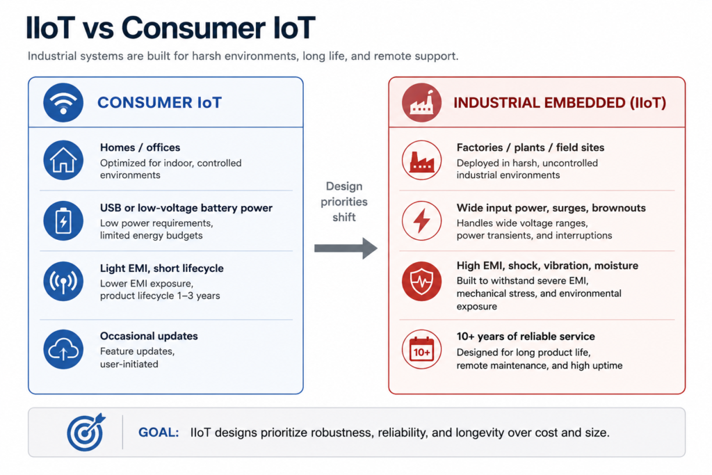
Aspect
Consumer IoT
Industrial Embedded (IIoT)
Environment
Homes, offices (indoor, climate-controlled)
Factories, plants, outdoor sites (dust, moisture, shock)
Power
USB/5V, Li-batteries (stable, low voltage)
Wide-range DC/AC (e.g. 9–36V DC, 85–305VAC), generators, battery/UPS
EMI/EMC
Low ambient noise
High noise (motors, drives, welders) – must meet IEC 61000 industrial EMC standards
Temperature Range
~0–50°C
−40°C to +85°C (or beyond)
Ingress Protection
Minimal (plastic cases)
Rugged metal enclosures, high IP ratings (IP65–IP67), conformal coating, sealed connectors
Connectivity
Wi-Fi, Bluetooth (consumer protocols)
Industrial buses (CAN, RS-485), Ethernet (with isolation/PoE), cellular or LPWAN radios
Lifetime
~2–5 years, replaceable/upgradable
10–20+ years with continuous service and support
Diagnostics
Occasional user reset, OTA updates via apps
Always-on health telemetry, watchdogs, detailed logs, secure remote firmware update
Cost/Priority
Consumer price-sensitive
Reliability and robustness prioritized over cost
Leave a Reply